- XJTAG Insights
- Posts
- JTAG: To Chain or Not to Chain
JTAG: To Chain or Not to Chain
Paul Stinson - Applications Engineer
July 16, 2025
Welcome reader!
The design of the JTAG test interface allows for multiple devices to be connected in a daisy-chain arrangement. This means that you only need to run four signals from off-board to get full boundary-scan test capability. But just because you can connect all of the JTAG devices on your board in single chain, does that mean you should? In this article, we’ll take a look at the advantages associated with daisy-chaining and also with not daisy-chaining JTAG devices, and finish off with XJTAG's recommendations.
What is a JTAG chain?
Throughout XJTAG's software suite and documentation, we make many references to JTAG "chains". But how exactly would we define a chain? A good definition would be:
One or more JTAG compatible devices appearing between a TDI/TDO pair of the JTAG controller, as well as any inter-connecting components in this path, such as resistors, buffers, switches, etc.
While "chains" with only one device will generally all look the same, there are various ways of chaining together multiple JTAG devices. The IEEE 1149.1 standard, which defines the JTAG interface and its usage for boundary-scan test, offers a few examples. The first example given is by far the most common way daisy-chaining gets implemented, with the JTAG devices sharing TMS and TCK signals, and passing the data signal from the TDO on one device to the TDI on the next, as shown in figure 1:
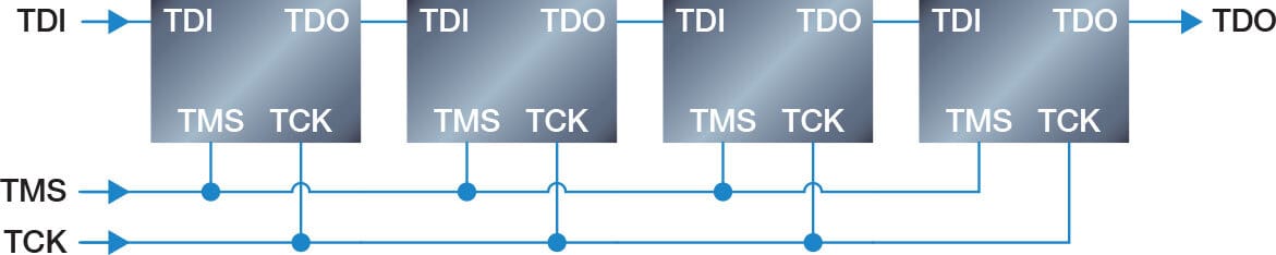
Figure 1: Serial connection using one TMS signal
The standard does offer some other possibilities as well though, including having two chains in parallel, whilst sharing a single TDI connection, with each half controlled by a separate TMS line:
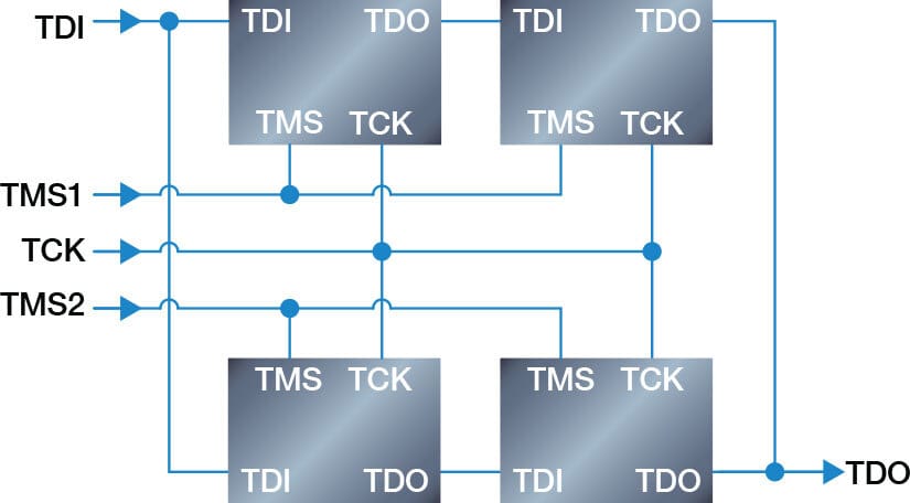
Figure 2: Serial/parallel connection using two TMS signals
Or by sharing TMS and TCK lines, but giving each device its own separate TDI connection:
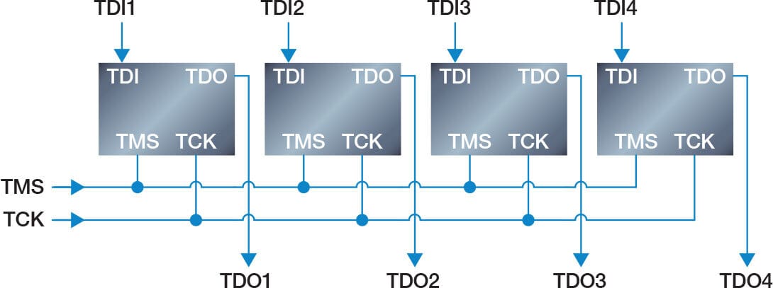
Figure 3: Multiple independent paths with common TMS and TCK signals
Even more variations are possible, sharing different numbers and types of JTAG signal and arranging the devices in different ways. But generally, any arrangement other than the first example increases complexity and could cause reduced test performance or compatibility issues with boundary scan test tools (XJTAG or otherwise), so XJTAG only recommends the simple serial arrangement as shown in Figure 1 when connecting multiple devices in a JTAG chain.
Should you daisy-chain your JTAG devices?
Advantages of daisy-chaining
Lower TAP requirements for JTAG controller: JTAG test controllers will have a maximum number of Test Access Ports (TAPs - a complete set of TDI, TDO, TMS and TCK signals) that they can control. If the number of JTAG devices on your board exceeds the number of TAPs your controller can drive, you will have to daisy-chain some of your JTAG devices to achieve maximum test coverage on the board. Additionally, there may be a lower cost associated with JTAG controllers that support fewer TAPs and so designing your board to require less TAPs may give the opportunity for cost savings when purchasing your test equipment.
Less off-board cabling: If the JTAG devices are connected together on the board, it is not necessary to either chain them together or connect them individually to the JTAG controller with an off-board wiring harness. Only a single off-board connection would be required, for the connection of one TAP to the JTAG controller. This can lead to better signal integrity for the JTAG signals and may allow shorter test times if the JTAG interface can be clocked faster.
Fewer connections to make to DUT: If only one TAP connection needs to be made to the board for boundary-scan testing to take place, this could mean fewer operations for a test operator to perform per DUT (only plugging/unplugging one connector) and therefore higher throughput in a production-line environment. Additionally, if the TAP connection is being made using test-points and test-probes in a fixture setup, using only one TAP means fewer probes are required and cost and complexity of the fixture can be reduced.
Advantages of not daisy-chaining
More useful test output on faulty boards: With a fully daisy-chained arrangement, a single faulty JTAG device or bad connection somewhere along the chain can result in zero ability to test the board. By analysing the data that is returned from the chain, it may be possible to determine which device or connection may be breaking the chain. But with individual connections to the JTAG controller for each device, faulty devices can be identified immediately and tests can still be run with all remaining boundary-scan access, the results of which could make identifying over-arching faults much easier. This also applies to prototype bring-up scenarios, where one mistake in the design of your chain could prevent you from utilising boundary-scan tools for troubleshooting.
Support for inter-device power-up dependencies: In a situation where one JTAG device sequences or otherwise enables power supplies that are required for another JTAG device to be used, daisy-chaining all of the JTAG devices is not possible. Having individual TAP connections from all JTAG devices (or at least the ones that control power rails) is necessary, so that these devices can be brought under boundary-scan control first and appropriate signals driven to allow the other devices to power up.
Ability to run all devices at maximum rated TCK frequency: All JTAG compatible devices have maximum test clock (TCK) frequencies specified by the device manufacturer, that test equipment should not exceed for reliable operation. These speeds can vary significantly, from a few megahertz, to tens of megahertz. A fully daisy-chained arrangement of JTAG devices is limited to the lowest rated frequency of all of the devices in that chain, however with individual connections to the JTAG devices, it is possible to run each at its maximum rated frequency, scanning data into the devices in parallel. This can also result in reduced test time, particularly in designs where large pin count devices with high maximum TCK frequencies exist alongside devices with lower maximum frequencies. In XJTAG, this feature is called "Optimised Scans".
Ability to scan data in parallel: Even if the JTAG devices all have the same maximum TCK frequency, running multiple chains simultaneously in parallel allows the data to be loaded much faster, from twice as quickly with two chains, up to eight times faster with eight chains. With careful balancing of the different chain lengths, this can lead to significant reductions in test time.
Board design may already lend itself to individual connections: Many devices that feature JTAG will use the interface for programming or debugging operations, as well as supporting boundary-scan test, and some tools used for these tasks may not be able to cope with multiple devices in a chain. In this case, it is fairly common for the JTAG interface of MCUs or FPGAs to already be broken out on a header close to the device, to allow easy connection of programming and debugging tools during firmware development. When reusing these connectors for boundary-scan test, it is much easier to connect each one to a single TAP on the controller, than to create a wiring harness that connects them in a chain.
Easier and more flexible when testing multi-board assemblies: When testing product assemblies made up of multiple PCBAs, each with their own JTAG devices, it is more convenient to connect the boards to the JTAG controller individually then to daisy-chain the devices across the boards. Doing so would require careful planning in the design stage, to allow extra pins in board-to-board connectors for carrying JTAG signals between boards, or the creation of a wiring harness that connects the chains of each board into one long chain. In both cases, you lose the flexibility to test the assembly with some boards missing or test individual boards in the assembly, purely through inclusion of different TAPs in software. You would always need a full set of boards to run the tests, or you need additional hardware such as relays to allow you to complete the chain with boards missing.
Simplify designs with multiple JTAG logic levels: On a board featuring multiple JTAG devices, that operate their JTAG interface a different logic levels, a fully daisy-chained arrangement will require additional circuitry in the chain such as level shifters or voltage dividers. In a setup with reduced daisy-chaining (or no daisy-chaining) this additional complexity can be avoided by only connecting devices with the same JTAG logic level in the same chain and configuring a matching logic level on the connected TAP of the JTAG controller. This does require the JTAG controller to support different logic levels on different TAPs, but this feature is provided by all of XJTAG’s current JTAG controllers.
Conclusions and XJTAG recommendations
While there are some advantages to connecting all of your JTAG devices in one long chain (mostly around minimising connections to the DUT and working within the limits of your JTAG controller), the advantages in flexibility, fault tolerance and simplicity of connecting all devices to a separate TAP outputs on the controller will generally outweigh them. Signal integrity issues caused by additional off-board wiring can be avoided with good practices for creating wiring harnesses or designing test fixtures, meaning it should generally be possible to clock JTAG chains at the same frequencies as when they are daisy-chained on the board, or faster if features like Optimised Scans are used.
If your JTAG controller can drive enough TAPs, XJTAG would generally recommend to put every JTAG device on its own chain. Failing this, minimising the number of devices per chain would be the best option, grouping devices by JTAG logic level to avoid introducing level shifters to the chain. Consideration of power-up dependencies is also essential and JTAG devices that enable power for other JTAG devices should always be on a different chain to the devices they need to power-up.
XJTAG offers JTAG controllers with up to eight TAP outputs, which will be enough for most designs to adhere to this guidance. For further design-for-test (DFT) and boundary-scan educational resources, see XJTAG.com.
Explore free XJTAG resources
From an Electronics Test Method Finder to Free Trials and Webinars.
Visit the website to see a range of free resources.
Enjoyed this update? Please forward to a colleague who may find it interesting.